Carbon Paper and Carbon Cloth Gas Diffusion Layers: What’s the Difference?
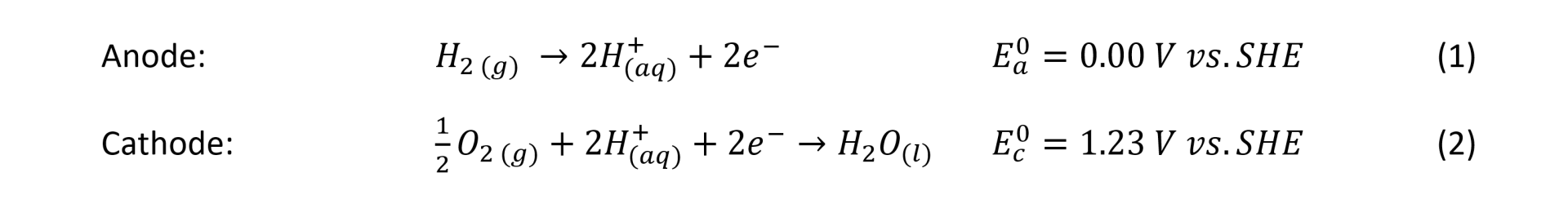
Fuels cells rely on the effective diffusion of hydrogen and oxygen gasses through gas diffusion electrodes (GDEs). The GDEs are complex, porous structures with modulated porosity, and they optimise the diffusion of hydrogen for the hydrogen oxidation reaction (HOR) through the anode and oxygen, for the oxygen reduction reaction (ORR) through the cathode. Figure 1 shows a typical structure of the anode and cathode gas diffusion electrodes positioned on each side of a Solid Polymer Electrolyte (SPE) membrane forming a Membrane Electrode Assembly (MEA). In a fuel cell, the MEA is sandwiched between two bipolar plates, fitted with flow fields channels to deliver, among other functions, hydrogen, and oxygen gases to the GDEs.
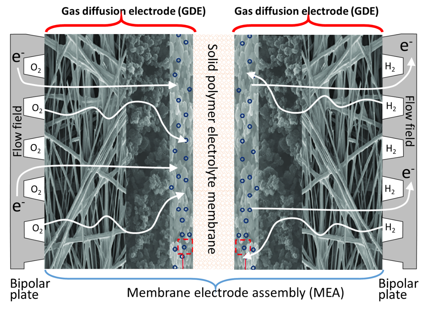
The figure shows that the role of the gas diffusion electrodes is to bring the gas reactants to the catalyst layer. However, their function also includes the water balance between the electrodes, for example providing water so that the protons generated from the HOR (equation 1) can migrate to the cathode through the SPE membrane. The gas diffusion electrodes also regulate the flow of water in liquid or vapour phase, formed during the ORR (equation 2). Careful management of the water balance also includes maintaining the SPE membrane well hydrated to keep its ionic conductivity high. Another function of the GDEs is to provide good electrical contact to transfer the electrons released from the hydrogen oxidation reaction at the anode, to the cathode via an external electrical circuit for the ORR. Another role of the GDEs is to transfer the heat generated from the reactions to the bipolar plates where it is transferred outside the cell and recovered.
The structure of a gas diffusion electrode, in Figure 2, shows that they typically consist of 1) a macro porous carbon diffusion layer of 100-500 mm thickness range, 2) a microporous layer (MPL) typically, 5-50 mm thickness and 3) a catalyst layer (CL) with around 1-20 mm thickness [1].
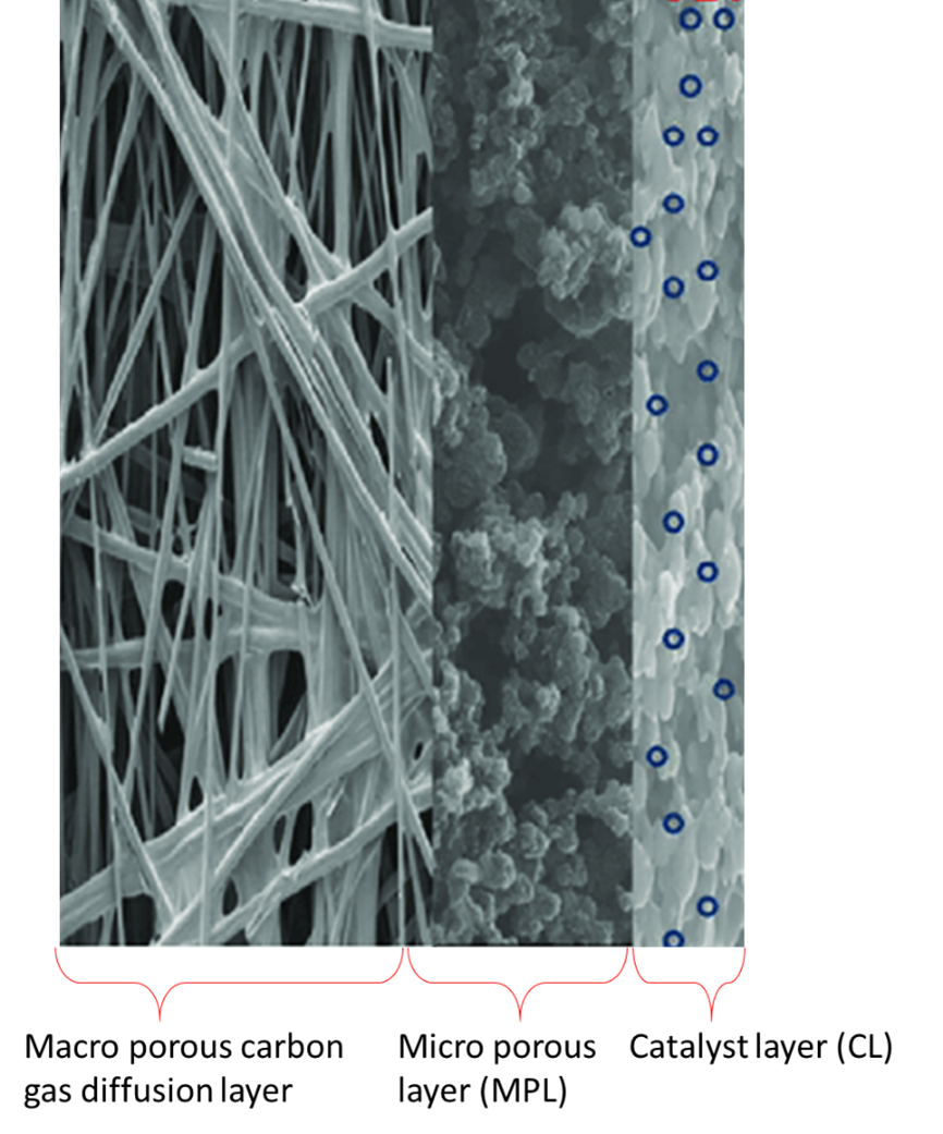
The macro porous carbon diffusion layer consists of carbon fibres manufactured as carbon paper (non-woven fibres) or carbon cloths (woven fibres). They provide high permeability for the gas reactants and mechanical supports for the microporous layer (MPL). The MPL is an important component of the GDEs because it helps to reduce the electrical resistance between the macro porous carbon diffusion layer and the catalyst layer (CL) by providing a uniform contact. The MPL consists of carbon particles of high surface area with some carefully controlled hydrophobicity provided by PTFE particles, although many researchers use Nafion to provide ion conduction additionally. The macro porous layer formed of carbon paper or carbon cloth, on the other hand, is less hydrophobic that the MPL, with larger porous sizes. Despite using carbon paper or carbon cloth in the manufacture of GDEs, many research groups investigating these materials agree that the combination of modulated porosity and hydrophobicity is beneficial for the optimal flow gas distribution and moisture in the fuel cell and benefits its performance [2].
Carbon fibres are strong, light weight, and can be produced from petroleum, coal, cellulose, or phenolic resins but the most common materials for fuel cells seems to be a copolymer containing over 90% of polyacrylonitrile (PAN). Figure 3 shows the routes to produce carbon paper or carbon cloth from PAN fibres made by a solvent spinning process.
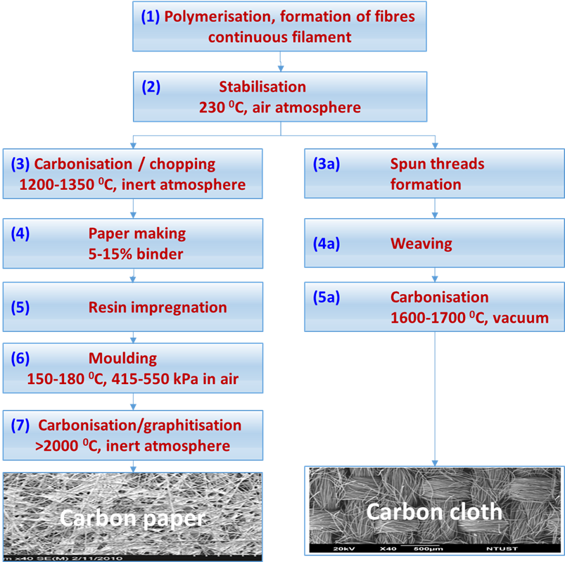
The numbers in blue in the following text, refer to Figure 3. The polymerisation process (1) produces long carbon filaments of 12-14 mm diameter that are stabilised at 230 oC in air (2) and further carbonised at 1200 -1350 oC in nitrogen atmosphere (3) reducing their diameter to around 7 mm due around 50% loss weight yielding a fibre with 50% carbon. In preparation for paper making [4], the fibres are chopped to 3-12 mm length and mixed with a binder (4) and prepared as rolls where the carbon paper finish thickness is approximately 0.20-0.27 mm. The carbon paper is impregnated with thermoset resins (5) and subsequently pressed to moulded to the desired thickness and density at 175 oC and 415-550 kPa pressure (6). The final carbonisation/graphitisation step at over 2000 oC creates crystalline graphite sheets with 99% carbon that poses high electrical and thermal conductivity, chemical resistance, and fibre diameter of roughly 6.5 mm. The resultant product is immersed in 25% PTFE aqueous solution for 3 min followed by heat treatment at 350 °C for 30 minutes to provide some hydrophobicity but maintaining its high electrical conductivity. The carbon paper is rigid and fragile and must be handle with care when preparing GDEs and when compressed between the bipolar plates of a fuel cell stack [5, 6].
The preparation of carbon cloth uses similar initial process, the long carbon filaments generated by the polymerisation (1) and stabilised at 230 oC in air (2) are spun (3a) to form fibre bundles or yarns that are later woven by intercalating each other at right angles to form a carbon textile (4a). The woven formation keeps the carbon textile mechanically strong without the need of a resin impregnation, as in the case of carbon paper manufacturing, and it is further carbonised at 1600-1700 0C in vacuum (5a). Figure 3 also shows some images of the final appearance of carbon paper and carbon cloth where the structural differences can be clearly appreciated.
|
Property |
Method |
Carbon paper a |
Carbon cloth b |
|---|---|---|---|
|
Thickness |
Callipers, 7 kPa |
0.19 mm |
0.34 mm |
|
Areal weight |
Gravimetric |
85 g m-2 |
118 g m-2 |
|
Density |
At 7 k Pa |
0.45 g m-3 |
0.31 g m-3 |
|
Resistance through a plane |
Between two graphite plates at 1.3 MPa |
0.009 W cm-2 |
0.005 W cm-2 |
|
Bulk resistivity (through plane) |
Mercury contact |
80 × 10-3 W m |
NA |
|
Bulk resistivity (in-plane) |
Four-point probe |
5.5 × 10⁻³ W m |
9 × 10⁻³ W m |
|
Apparent electrical resistivity. |
|
6 × 10⁻³ W m Sigratherm GFD5 [10] |
(4.7–6.9) × 10−3 W m Sigratherm GFD5 [7] |
|
Porosity |
|
60-80% |
95% |
|
Use |
|
Batteries, water Treatment, sensors, electrochemical Capacitors, catalyst support: |
Redox flow batteries, fuel cells, metal recovery, electrosynthesis, bio-electrochemistry. |
|
Manufacture |
|
Paper making process follow by carbonisation |
Woven process |
|
Appearance |
|
Anisotropic randomly dispersed fibres Mechanically fragile, easily broken |
Textile like with orderly crosslinked fibres. Mechanically strong. |
Table 1. a) Toray TGP-H-060 paper, b) Ballard material Avcarb 1071 HCB. Adapted from [3, 7, 10].
Physical properties that establish the difference between the two types of macro porous diffusion layers include porosity, mean pore radius, specific surface area, tortuosity, gas and permeability, electrical resistance, among others. Table 1 is a list of the most common properties found in the literature. These properties are important to maintain the optimal transport of water and gas and are likely to change during the operation and clamping process of the MEA into the fuel cell stack. One of the main issues with carbon paper or carbon cloth is the water transport, if flooding occurs, i.e., if water accumulates in the channels designed for gas transport or in the flow fields, the gas must be dissolved in water before it can react on the catalyst layer, causing a significant decrease in performance. Therefore, the hydrophobicity of the different layers that constitute the gas diffusion electrode must be carefully tailored for the adequate liquid and gas transport to and from the GDEs. Although their porosity ranges between 70% and 95% some literature suggest that carbon cloth has higher porosity in general and less water saturation resulting in higher performance that carbon paper [8, 9]. The structure of carbon cloth seems to be less tortuous and is more efficient to release water than carbon paper making it suitable for high humidity working conditions whereas carbon paper retains more water and is more suitable for drier environments [10]. Some literature suggest water flooding can occur in the gas diffusion layers when their mean pore diameter is greater than 30 mm [11, 12].
The use of carbon paper or carbon cloth for the manufacture of the diffusion electrodes affects the performance of the fuel cell. For example, when carbon cloth is used, the pressure drop on the flow fields is likely to be higher due to higher intrusion of the cloth into the flow filed channels which reduce their hydraulic diameter. Figure 4 shows a photograph that demonstrates the slight reduction of the flow field channel when carbon cloth (b) is used, in comparison with the use of carbon paper (a).
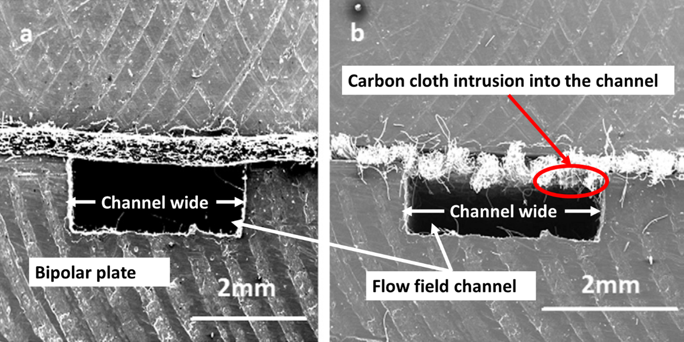
The intrusion of the carbon paper or carbon cloth into the flow field channel increases if the channel is wider and it is lower for carbon paper than for carbon cloth perhaps because carbon paper is more rigid, and the resin helps to maintain the mechanical stability of the fibres. Carbon cloth intrusion in the flow field channels can be between 43–125% higher than carbon paper which could cause an uneven distribution of reactants. Figure 4 shows this effect when carbon paper and carbon cloth are compressed between two bipolar plates.
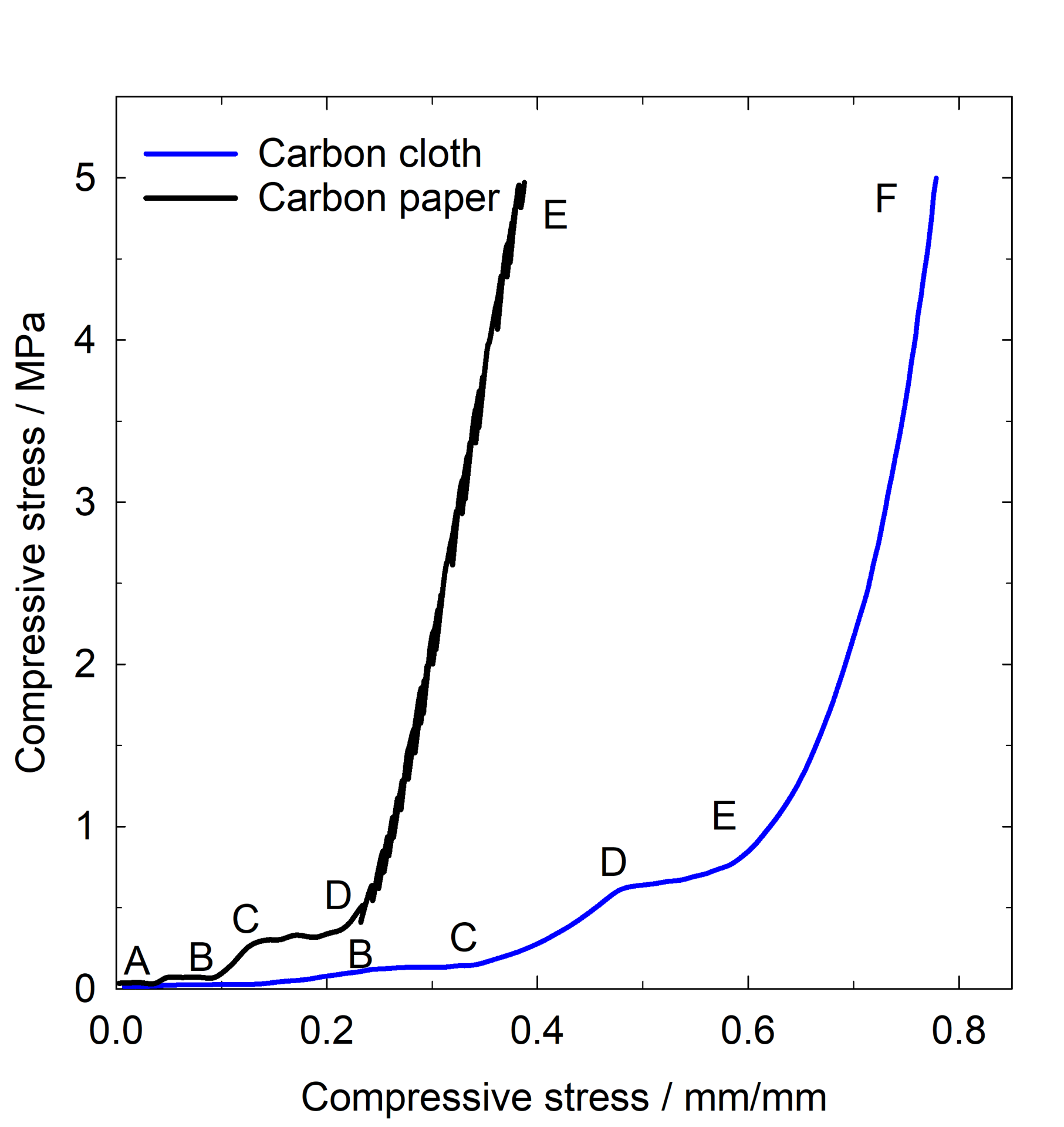
The compression of a porous structure starts with an elastic deformation followed by a plateau when the volume of the porous decrease, this is followed by porous densification as the compression increases. These stages can be observed on carbon paper in Figure 5. The transition from plateau AB to plateau CD occurs gradually due to the reduction of the air gaps in a large pore size distribution within the carbon paper. As the compression continues, carbon paper enters the densification stage from D to E. For carbon cloth, with a different topography and larger pores than the carbon paper, the behaviour is similar, but it extends over wider diameter and in the region E to F the densification occurs. Carbon cloth and carbon paper are structurally different and that is reflected in the different shapes of the strain stress curves for example at applied stress of 5 MPa the stress compressibility for carbon paper is 0.39 mm/mm whereas for carbon cloth is 0.78 mm/mm suggesting that carbon paper is more rigid whereas carbon cloth lacks compression rigidity [14].
Another important parameter of carbon paper and carbon cloth is their through-plane resistivity, which evaluates the resistance to current flow through the thickness of the macro porous carbonaceous material. In addition to the through-plane resistivity, the in-plane resistivity, which is a measure of the resistance to current flow across the surface is also a crucial parameter. Both terms are fundamental for the good performance of fuel cells because high resistivity values will increase the potential drop across the electrodes. Compression reduces the porosity for both carbon paper and carbon cloth and consequently through-plane and in-plane resistivities decrease favouring the fuel cell performance, but it also depends on the alignment of the carbon fibres in both materials.
Conclusion
Fuel cells operating with carbon paper or carbon cloth might be suited to different environments: while carbon paper is rigid and is not good handling high relative humidity, carbon cloth is more suited to high humidity environments; however, it lacks rigidity and is prone to reduce the depth of the channels in the flow field plate, which might increase the gas pressure drop to the detriment of the fuel cell performance. This paper showed the most basic characteristics of carbon paper and carbon cloths, their manufacturing process, and some of the most relevant characteristics and differences. For more detailed descriptions and fundamental theory, please refer to the references cited below.
Carlos Ponce De Leon Albarran
Professor of Electrochemical Engineering

Carlos Ponce de León is Professor in Electrochemical Engineering at the University of Southampton. His main areas of expertise include electrochemical energy conversion and water treatment technology, recovery of precious metals and fuel cell testing. Carlos is Principal Investigator of projects funded by the European Commission, and has organised conferences in electrochemistry, electrochemical engineering. He has authored over 200 peer-reviewed publications with an h-index of 51, with over 10,500 citations.
References
- Weber, A.Z. and Newman, J., Chem. Rev., 2004, Vol. 104, p. 4679.
- Yu. G. Chirkov, V. I. Rostokin. Cathode of a Fuel Cell with a Solid Polymer Electrolyte: Calculating Overall Currents in the Presence of a Gas-Diffusion Layer. Russian Journal of Electrochemistry, 2007, Vol. 43, No. 1, pp. 25–33.
- M.F. Mathias, J. Roth, J. Fleming, W. Lehnert, in Handbook of Fuel Cells, Fundamentals; Technology and Application, Vol. 3, Chapter 42. Wolf Vielstich, Arnold Lamm, Hubert Gasteiger (eds.) New York: John Wiley & Sons; 2003.
- Orlando J. Rojas and Martin A. Hubbe. The Dispersion Science of Papermaking. Journal of Dispersion Science and Technology Vol. 25, No. 6, pp. 713–732, 2004.
- Hyunuk Kim, Young-Ju Lee, Gu-Gon Park, Seok-Hee Park, Yoon-Young Choi, Yoonjong Yoo. Fabrication of carbon paper containing PEDOT:PSS for use as a gas diffusion layer in proton exchange membrane fuel cells. Carbon, Vol. 85 (2015) 422 –428.
- Hyunuk Kim, Young-Ju Lee, Dong-Chul Lee, Gu-Gon Park, Yoonjong Yoo. Fabrication of the carbon paper by wet-laying of ozone-treated carbon fibers with hydrophilic functional groups. Carbon, Vol. 60, August 2013, Pages 429-436.
- N. Vatistas, P. F. Marconi and M. Bartolozzi, Electrochim. Acta, 1991, 36, 339.
- Kowal JJ, Turhan A, Heller K, Brenizer J, Mench MM. Liquid water storage, distribution, and removal from diffusion media in PEFCS. J Electrochem Soc. 2006;153(10):A1971–8.
- Mukundan R, Lujan RW, Davey JR, Spendelow JS, Hussey DS, Jacobson DL, et al. Ice formation in PEM fuel cells operated isothermally at sub-freezing temperatures. ECS Trans 2009;25(1):345–55.
- Wang Y, Wang CY, Chen KS. Elucidating differences between carbon paper and carbon cloth in polymer electrolyte fuel cells. Electrochim Acta 2007;52:3965–75.
- M.S. Wilson, J.A. Valerio, S. Gottesfeld, Electrochim. Acta 40 (1995) 355.
- H. Ostadi et al. / Journal of Membrane Science 351 (2010) 69–74.
- Vijay Radhakrishnan, Prathap Haridoss. Differences in structure and property of carbon paper and carbon cloth diffusion media and their impact on proton exchange membrane fuel cell flow field design. Materials and Design 32 (2011) 861–868.
- Escribano S, Blachot JF, Eth‘eve J, Morin A, Mosdale R. Characterization of PEMFCs gas diffusion layers properties. J Power Sources 2006;156:8–13.