Air Cooled v Liquid Cooled PEM Fuel Cell Stacks
Why Do We Need Cooling For Fuel Cell Stacks?
Proton exchange membrane fuel cells (PEMFCs) convert the chemical energy of hydrogen and oxygen to electricity and water. This process also releases heat, which is generated due to:
- Reversible heat of reaction: Entropic heat of reaction which is the difference between the total Gibbs free energy and the enthalpy change during the reaction.
- Irreversible heat of reaction: Heat produced due to the losses associated with reaction kinetics and species transport.
- Ohmic heating: Heat produced due to ion transport in the polymer membrane and ionomer and electron transport in the cell.
- Phase change: Heat released or absorbed due to phase change of water in the cell.
- Heat of water sorption: Sorption/desorption of water into the polymer ionomer in the anode and cathode catalyst layers results in heat dynamics. During steady state operation, the heat of sorption/desorption is equal and opposite between the two catalyst layers and therefore, does not impact the overall heat generation in the cell [1].
In general, the total heat flux (q in W/cm2), can be written as q = (Etn − Ecell)i, (1) where Ecell is the cell voltage, i is the current density, and Etn is the thermoneutral voltage which represents the imaginary maximum voltage of a fuel cell assuming all the enthalpy change of the reaction is converted to electricity. The thermoneutral voltage can be computed using the high heating value of the reaction (assuming product water in liquid phase) as 1.48 V or using the low heating value of the reaction (assuming product water in vapor phase) as 1.25 V at standard conditions (25 ◦C, 1 atm).
Based on Eq. (1), it is evident that the total heat produced by the fuel cell during operation increases with an increase in the active area (which also increases with number of cells in a stack) and current density. Although the reaction kinetics are favored by an increase in temperature of the cell due to the heat produced, drying out of the membrane resulting in large ohmic losses and subsequent membrane degradation outweigh any potential gains from the reaction kinetics improvement. Therefore, for efficient and stable operation of the PEMFC, the stack or cells must have an effective cooling system that removes the waste heat generated during the operation so that a desired temperature profile (uniform or gradient) can be maintained.
Cooling Techniques for PEM Fuel Cell Stacks
Cooling techniques for PEMFC stacks can be broadly classified into two categories based on the working fluid, i.e., air-cooled, and liquid-cooled. The following sections discuss salient features of the two cooling methods, including criteria for selection (e.g. stack power rating), cost of the system, and efficiency of heat removal to achieve the desired temperature distribution.
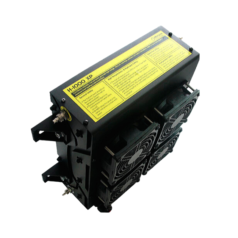
Air Cooling for PEM FC stacks
Air-cooled fuel cell stacks use an ambient air stream directed through cooling plate flow channels to remove the heat produced from the stack. Since air is supplied to the cathode of a PEMFC, the use of air cooling simplifies the system design by using the common air supply and subsequently, venting of the hot air along with the PEMFC exhaust. It must be noted here that the cooling air supply should be separated from the cathode air supply to prevent excessive water loss from the cell which can dry out the membrane. Air cooling is suitable for 100 W to 2-5 kW stacks [2]. For stacks with power output greater than 5 kW, the efficiency of air cooling (in terms of stack temperature distribution from inlet to outlet) reduces significantly due to the low thermal conductivity and low specific heat capacity of air.
Air-cooled stacks have been proposed for automotive and portable power applications. Studies show that for smaller stacks (< 5 kW) the blower power consumption to supply cooling air is less than 3% making air cooling particularly attractive for smaller stacks. Recent studies further demonstrate the feasibility of using air-cooled stacks for stationary power applications using 2.5-7.5 kW stacks. For the 7.5 kW stack operated at ambient temperature, air cooling resulted in a wide distribution of average temperature in stack ranging from 22.1 to 51.4 ◦C and 20.8 to 33.6 ◦C with fan speeds at 20% and 80% rated capacity, respectively [6]. Additionally, temperature hotspots were observed near the outlet with the stack temperature increasing to 57 ◦C for currents in the range of 20-40 A. Air cooling at lower fan speeds which resulted in large temperature increase in the stack was also found to improve the performance due to an improvement in reaction kinetics and water management. Although air cooling might produce large temperature variations between the inlet and outlet of the stack, optimization of the air flow can be used to maximize cell performance by introducing temperature gradients to improve water management in the stack, particularly for stationary applications. To obtain a more uniform temperature distribution in the stack, scientists increased the size of the cooling flow channels while maintaining the same pressure drop. They also proposed reducing the thickness of the cooling plates to improve the cooling efficiency, but this would result in an increase in the pressure drop.
Other studies have also investigated air cooling of 1.2 kW PEMFC automotive stacks and demonstrated the large temperature variations in the stack. Jun Okano reported an increase in cell temperature by nearly 9 ◦C within two hours while using air cooling which resulted in a drop in the overall stack efficiency.[8] Kap-Seung Choi has also showed that a change in ambient temperature had a significant impact on the PEMFC stack power and efficiency due to a loss in cooling efficiency while the humidity of the ambient air was found to have no impact on the cooling characteristics. [10]
Air cooling systems are unsuitable for large stacks due to the limited heat removal capacity of air and the considerable dependency on the ambient temperature. Additionally, the large temperature variations resulting from air cooling would hinder the power and efficiency of an automotive stack that operates at higher temperatures (nearly 80 ◦C) and under dynamic load conditions.
Liquid Cooling for PEM FC stacks
Liquid cooling is a much more suitable option for PEM fuel cell stacks with rated power greater than 5 kW. This is due to the higher heat capacity and thermal conductivity of liquids which results in a higher heat transfer coefficient compared to air for the same pumping power. For PEMFC stacks, the most common liquid coolant is deionized water. In automotive applications, a mixture of water and ethylene glycol, which is an antifreeze and suitable for sub-zero operation, is often used.
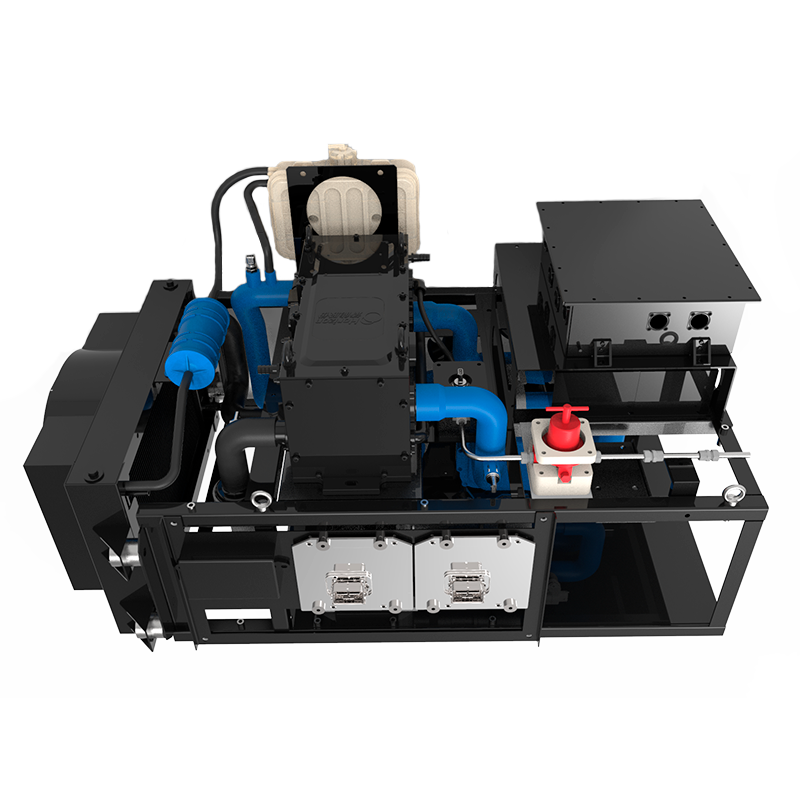
Compared to air cooling, liquid cooling has several advantages, such as higher cooling load and higher cooling efficiency resulting in better control over the stack temperature. However, liquid cooling requires additional components for the development of a cooling loop and higher pumping power resulting in additional parasitic losses. The coolant loop design is a particularly important concern for automotive PEM fuel cell stacks. This is due to the design considerations for the radiator size while meeting the stringent US Department of Energy Target which requires a heat rejection rate of 1.45 kW/◦C temperature difference between the coolant temperature at stack outlet and ambient temperature. For automotive applications, liquid cooling also increases the thermal mass to be heated during cold start conditions.
Similar to air cooling, liquid cooling is also achieved by flowing the liquid through a coolant plate with flow channels. Therefore, optimization of the flow field configuration and channel geometry has been a major area of research to maximize cooling efficiency, i.e., uniform temperature distribution across the stack, while minimizing the pressure drop to reduce the pumping power required. Generally, serpentine flow configuration results in a higher heat removal rate, more uniform temperature distribution (described by the index of uniform temperature), and lower maximum temperature (local hotspots in the PEMFC) compared to a parallel flow configuration [12, 13, 14]. However, the pressure drop in serpentine flow configuration is significantly higher than parallel flow configuration (1-2 orders of magnitude) which increases the coolant pumping power. To further improve the heat removal rate, especially under the ribs of the flow field, the convection enhanced serpentine flow field (CESFF) and multi-pass serpentine flow field (MPSFF) designs have been developed [15] [16]. These designs increase the coolant flow length and residence time in the coolant plate to increase the heat transfer rate from the cell and achieve a more uniform and lower average temperature in the cell. In addition to the flow configuration, the relative direction of the coolant flow with respect to the reactants (air and hydrogen) has also been shown to affect the temperature distribution in the PEMFC stack [17, 14]. For serpentine flow channels, coolant flow going across and in the same direction as the reactants was found to result in the most uniform temperature distribution in the cell [14]. For parallel flow channels, co-flow of the coolant and cathode air provided the most uniform temperature distribution [14, 17]. Although the uniformity of the temperature distribution in the stack (measured as a deviation from the average temperature) for the optimal flow configurations, was similar for serpentine and parallel channels, the maximum temperature in the cell was much higher (70 ◦C v/s 63.9 ◦C) for the parallel coolant flow configuration [14]. In addition to serpentine and parallel flow channels, porous metal foams have also been proposed for coolant flow plate design [18, 19]. Metal foams were found to have cooling efficiency better than parallel flow configurations (but worse than serpentine flow configuration) with lower pressure drop compared to serpentine flow field [18]. However, additional research is needed for the optimization of the metal foam permeability and machinability for applications in large PEMFC stacks.
While the flow configuration has an overall impact on the path and distribution of the coolant, the flow channel geometry also impacts the flow rate, pressure drop, and heat transfer coefficient of the coolant. Due to the low pressure drop associated with parallel flow configuration, wavy, zigzag and non-uniform channel cross-sections have been used to increase the cooling efficiency by reducing the maximum temperature [20] [21], [22]. The non-uniform channel geometry resulted in a reduction in the maximum temperature, and a more uniform temperature distribution while also reducing the pressure drop. Although a non-uniform channel design might be more efficient in terms of cooling and parasitic losses, the machining and optimization of these designs for PEM fuel cell stacks might be challenging. Channel geometries have also been modified to induce 3D chaotic flow in the channels to increase the heat transfer coefficients [23, 24, 25]. C, B, U, V, and 3D zigzag channel designs have been proposed to increase the heat transfer coefficient of the coolant [23, 24, 25]. Among these designs, C and V shaped channels showed the most optimal performance in terms of cooling efficiency and pressure drop [25]. The V shaped coolant channel design was also used for the fuel cell in the Honda Clarity [26].
Coolants Used in PEM Fuel Cell Stacks
A mixture of water and ethylene glycol is typically used as the coolant for PEM fuel cell stacks. The coolant should have a low electrical conductivity such that there is no shunt current between the cells which reduces the PEMFC efficiency. During the operation of the PEMFC, contaminant collection on the bipolar plates and oxidation of glycol can result in the coolant becoming electrically conductive [27]. Nanofluids, comprising of the base fluid with suspended nanoparticles, introduced by Mohapatra [28] seek to suppress the coolant electronic conductivity while increasing the heat transfer coefficient. Commercial nanofluid coolant, Dynalene from Dynalete, contains organic inhibitors that bind to the walls of the plates and pipes protecting them from corrosive attacks, and a polymeric ion suppressant to scavenge and neutralize free ions in the coolant. Nanofluids with different nanoparticles, such as Al2O3, CuO, TiO2, SiC, and graphene, have been studied for their stability, thermal conductivity, electrical conductivity, and viscosity. These fluids offer much higher thermal conductivity (up to 300% higher) and heat transfer coefficients (increase of up to 160%) [30] but have higher viscosity which can increase the pumping power required for the coolant [29]. However, the higher heat transfer coefficient of the nanofluids might reduce the total coolant volume thereby reducing the pumping power. The stability of the nanofluids is also a major concern and therefore, system level investigations of these coolants are required to determine their feasibility for PEMFC stacks.
Phase Change Cooling in Fuel Cell Stacks
Phase change cooling uses coolant evaporation or boiling to remove heat from the PEMFC stack. For evaporative cooling, the boiling temperature of the coolant should be higher than the operating temperature of the PEMFC while for cooling through boiling, the coolant boiling point should be less than the PEMFC operating temperature. Two-phase flow instability and lack of a suitable working fluid make cooling through boiling challenging for low-temperature PEMFCs. For high-temperature PEMFCs, water has been demonstrated as a suitable coolant that can be used without a coolant pump. Evaporative cooling for low-temperature PEMFCs has been achieved through direct liquid water injection into the PEMFC stacks and has been shown to work effectively for stacks ranging from 500 W to 75 kW [31]. Porous wicks and water transport plates have also been used to demonstrate evaporative cooling in PEMFC stacks [31] Recently, a novel approach for evaporative cooling was developed by Cochet and co-workers [32, 33] where patterned gas diffusion layers (containing hydrophilic and hydrophobic regions) were used on the anode to facilitate liquid water injection and transport to the catalyst layers. Using this approach, the authors reported heat removal rates higher than 1 W/cm2. Evaporative cooling also results in internal humidification of the cell. The main drawback of this technique is the lack of control of the evaporation rate which is governed by the local cell environment.
Conclusion
In summary, liquid cooling provides high cooling efficiency and heat removal rate but requires an additional coolant system comprising of a pump and heat exchanger. For automotive applications, this affects the stack efficiency, design of operating conditions, system size, and radiator size. Optimization of the flow configuration and channel geometry and the development of nanofluids could further increase the efficiency of liquid cooling for PEMFC stacks.
Mayank Sabharwal
Assistant Professor at the University of Calgary

Mayank Sabharwal is an Assistant Professor and Chair of Sustainable Hydrogen in the Department of Chemical and Petroleum Engineering at the University of Calgary. He received his PhD from the Mechanical Engineering Department at the University of Alberta in 2019. After his PhD, he was a postdoctoral fellow at Paul Scherrer Institute in Switzerland (from 2019 to 2021) and Lawrence Berkeley National Laboratory in USA (from 2021 to 2023). His current research focuses on material innovation and novel electrode architecture development for different electrochemical systems related to energy storage and hydrogen production and utilization. His research group develops operando imaging tools and multiscale numerical models to understand the transport processes in these systems.
References
[1] M Bhaiya, A Putz, and M Secanell. Analysis of non-isothermal effects on polymer electrolyte fuel cell electrode assemblies. Electrochimica Acta, 147:294–309, 2014.
[2] Andrew L Dicks and David AJ Rand. Fuel cell systems explained. John Wiley & Sons, 2018.
[3] H Schmidt, P Buchner, A Datz, K Dennerlein, S Lang, and M Waidhas. Low-cost air-cooled pefc stacks. Journal of Power Sources, 105(2):243–249, 2002.
[4] Young-Jun Sohn, Gu-Gon Park, Tae-Hyun Yang, Young-Gi Yoon, Won-Yong Lee, Sung-Dae Yim, and Chang-Soo Kim. Operating characteristics of an air-cooling pemfc for portable applications. Journal of Power Sources, 145(2):604–609, 2005.
[5] Jinfeng Wu, Stefano Galli, Ivano Lagana, Afonso Pozio, Giulia Monteleone, Xiao Zi Yuan, Jonathan Martin, and Haijiang Wang. An air-cooled proton exchange membrane fuel cell with combined oxidant and coolant flow. Journal of Power Sources, 188(1):199–204, 2009.
[6] Jun Shen, Changqing Du, Fuwu Yan, Ben Chen, and Zhengkai Tu. Experimental study on the dynamic performance of a power system with dual air-cooled pemfc stacks. Applied Energy, 326:120025, 2022.
[7] Mardit Matian, Andrew Marquis, and Nigel Brandon. Model based design and test of cooling plates for an air-cooled polymer electrolyte fuel cell stack. International Journal of Hydrogen Energy, 36(10):6051– 6066, 2011.
[8] Jun Okano, Yoshio Matsushita, and Keiichi Okajima. Evaluation of pefc stack performance and effects of cooling failure. ECS Transactions, 16(24):141, 2009.
[9] KP Adzakpa, Julien Ramousse, Y Dub´e, H Akremi, K Agbossou, M Dostie, A Poulin, and M Fournier. Transient air cooling thermal modeling of a pem fuel cell. Journal of Power Sources, 179(1):164–176, 2008.
[10] Kap-Seung Choi, Hyung-Man Kim, Hyung Chul Yoon, Matthew E Forrest, and Paul A Erickson. Effects of ambient temperature and relative humidity on the performance of nexa fuel cell. Energy Conversion and Management, 49(12):3505–3511, 2008.
[11] DOE TECHNICAL TARGETS FOR FUEL CELL SYSTEMS AND STACKS FOR TRANSPORTATION APPLICATIONS. https://www.energy.gov/eere/fuelcells/doe-technical-targets-fuel-cell-systems-and-stacks-transportation-applications.
[12] Jongmin Choi, Yoon-Ho Kim, Yongtaek Lee, Kyu-Jung Lee, and Yongchan Kim. Numerical analysis on the performance of cooling plates in a pefc. Journal of Mechanical Science and Technology, 22:1417–1425, 2008.
[13] FC Chen, Z Gao, RO Loutfy, and MJFC Hecht. Analysis of optimal heat transfer in a pem fuel cell cooling plate. Fuel Cells, 3(4):181–188, 2003.
[14] Mahmut Caner Acar. Modeling the influence of coolant flow directions on thermal performance of pem fuel cell cooling plates with serpentine and straight flow channels. Thermochimica Acta, 726:179560, 2023.
[15] Chao Xu and TS Zhao. A new flow field design for polymer electrolyte-based fuel cells. Electrochemistry Communications, 9(3):497–503, 2007.
[16] Jin Hyun Nam, Kyu-Jin Lee, Sangho Sohn, and Charn-Jung Kim. Multi-pass serpentine flow-fields to enhance under-rib convection in polymer electrolyte membrane fuel cells: Design and geometrical characterization. Journal of Power Sources, 188(1):14–23, 2009.
[17] Sanggyu Kang, Kyoungdoug Min, Fabian Mueller, and Jacob Brouwer. Configuration effects of air, fuel, and coolant inlets on the performance of a proton exchange membrane fuel cell for automotive applications. International Journal of Hydrogen Energy, 34(16):6749–6764, 2009.
[18] Ebrahim Afshari, Masoud Ziaei-Rad, and Zahra Shariati. A study on using metal foam as coolant fluid distributor in the polymer electrolyte membrane fuel cell. International Journal of Hydrogen Energy, 41(3):1902–1912, 2016.
[19] Mehdi Saeedan, Ebrahim Afshari, and Masoud Ziaei-Rad. Modeling and optimization of turbulent flow through pem fuel cell cooling channels filled with metal foam-a comparison of water and air cooling systems. Energy Conversion and Management, 258:115486, 2022.
[20] Shian Li and Bengt Ake Sunden. Numerical analysis on thermal performance of cooling plates with wavy channels in pem fuel cells. International Journal of Numerical Methods for Heat & Fluid Flow, 28(7):1684–1697, 2018.
[21] Ebrahim Afshari, Masoud Ziaei-Rad, and Mehdi Mosharaf Dehkordi. Numerical investigation on a novel zigzag-shaped flow channel design for cooling plates of pem fuel cells. Journal of the Energy Institute, 90(5):752–763, 2017.
[22] Shian Li and Bengt Sund´en. Numerical study on thermal performance of non-uniform flow channel designs for cooling plates of pem fuel cells. Numerical Heat Transfer, Part A: Applications, 74(1):917– 930, 2018.
[23] Yahia Lasbet, Bruno Auvity, Cathy Castelain, and Hassan Peerhossaini. A chaotic heat-exchanger for pemfc cooling applications. Journal of Power Sources, 156(1):114–118, 2006.
[24] Yahia Lasbet, Bruno Auvity, Cathy Castelain, and Hassan Peerhossaini. Thermal and hydrodynamic performances of chaotic mini-channel: application to the fuel cell cooling. Heat Transfer Engineering, 28(8-9):795–803, 2007.
[25] Cathy Castelain, Yahia Lasbet, Bruno Auvity, and Hassan Peerhossaini. Experimental study of the thermal performance of chaotic geometries for their use in pem fuel cells. International Journal of Thermal Sciences, 101:181–192, 2016.
[26] Shintaro Tanaka, Kenji Nagumo, Masakuni Yamamoto, Hiroto Chiba, Keiko Yoshida, and Ryu Okano.Fuel cell system for honda clarity fuel cell. ETransportation, 3:100046, 2020.
[27] Mohamed HS Bargal, Mohamed AA Abdelkareem, Qi Tao, Jing Li, Jianpeng Shi, and Yiping Wang. Liquid cooling techniques in proton exchange membrane fuel cell stacks: A detailed survey. Alexandria Engineering Journal, 59(2):635–655, 2020.
[28] Satish C Mohapatra. Fuel cell and fuel cell coolant compositions, November 21, 2006. US Patent 7,138,199.
[29] Irnie Zakaria, Z Michael, WANW Mohamed, AMI Mamat, WH Azmi, R Mamat, and R Saidur. A review of nanofluid adoption in polymer electrolyte membrane (pem) fuel cells as an alternative coolant. Journal of Mechanical Engineering and Sciences, 8:1351–1366, 2015.
[30] Mohammad Rafiqul Islam, Bahman Shabani, Gary Rosengarten, and John Andrews. The potential of using nanofluids in pem fuel cell cooling systems: A review. Renewable and Sustainable Energy Reviews, 48:523–539, 2015.
[31] Guangsheng Zhang and Satish G Kandlikar. A critical review of cooling techniques in proton exchange membrane fuel cell stacks. International Journal of hydrogen energy, 37(3):2412–2429, 2012.
[32] M Cochet, A Forner-Cuenca, V Manzi, M Siegwart, D Scheuble, and P Boillat. Novel concept for evaporative cooling of fuel cells: an experimental study based on neutron imaging. Fuel Cells, 18(5):619– 626, 2018.
[33] Michael Striednig, Magali Cochet, Pierre Boillat, Thomas J Schmidt, and Felix N Bu¨chi. A model based investigation of evaporative cooling for polymer electrolyte fuel cells–stack level analysis. Journal of Power Sources, 517:230706, 2022.