Fuel Cell Stack Assembly and Operation Explained
Introduction
Have you ever taken a hydrogen fuel cell bus or purchased a hydrogen fuel cell powered unmanned aerial vehicle and wondered, how is the hydrogen transformed into the electrical power required to drive the electric motors? The answer is using electrochemical reactions occurring inside a proton exchange membrane fuel cell (PEMFC) stack.
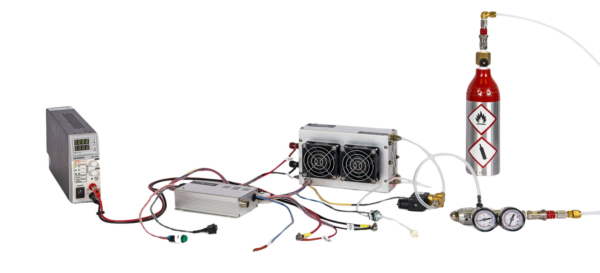
The fuel cell stack is the most critical component of any hydrogen fuel cell product. It is in this device that the energy in the hydrogen fuel is released by recombining with oxygen in the air to produce electrical current and water vapour. This is the device you need to purchase if you want to build your own electric motorcycle, back-up power generator, or small plane. All other components in your device are used to optimize the conditions under which the stack operates and are known as the balance of plant in a fuel cell system. This article is dedicated to describing how a PEMFC stack is assembled and how it works.
To understand how a fuel cell stack is assembled, it is useful to first think of your wireless keyboard, your TV remote control or a flashlight. Most of these devices are powered by several AA batteries. The reason for the use of multiple batteries is because each AA battery can only provide a voltage of about 1.5 V, depending on the exact battery chemistry, and to achieve higher voltages they must be connected in series, i.e., with the positive electrode of one battery connected to the negative electrode of the next, schematically [[- +][- +][- +]]. When connected in series, the voltage between the leftmost negative terminal and the rightmost positive terminal is the sum of the voltage provided by each battery, i.e., in the case of three batteries, the voltage would be about 4.5 V, i.e., 3 x 1.5V. A fuel cell stack is based on this same principle.
A hydrogen PEMFC stack is a device made of multiple proton exchange membrane fuel cells connected, or in other words “stacked”, in series to achieve a desired voltage. Most fuel cell, during normal operation provide 0.9 to 0.6 V, therefore, if you would like a PEMFC stack that produces 12 V, like a standard car battery, then you can stack between 18 to 20 PEMFCs in series, and use the voltage between leftmost negative electrode and the rightmost positive electrode.
Based on the description above, a fuel cell stack must be formed by two end plates that maintain all the cells in the stack together, usually under compression to minimize electrical contact resistances and gas leaks, two current collector plates to provide the positive and negative terminals of the stack, and a collection of PEMFCs. The next question is, how is a single PEMFC assembled and why?
PEM Fuel Cell Architecture and Operation
To understand how a single fuel cell is constructed, let’s discuss how a PEMFC works. In a hydrogen PEMFC, a proton conducting membrane (PEM) separates the hydrogen oxidation reaction, i.e., H2 -> 2H+ + 2 e-, that produces protons and electrons in the anode and the oxygen reduction reaction, i.e., ½ O2 + 2H+ + 2 e- -> H2O, that consumes protons and electrons in cathode. The proton conductive membrane is an insulator, so while the proton can easily travel from one side to the other of the membrane, electrons must move away from the membrane, thereby providing the electrical current to power your device. The voltage is due to the different energy of the produced electrons in the fuel cell. You might be wondering, but what if the oxygen and the hydrogen mix? The membrane is nearly impermeable to gases; therefore, the two gases cannot interact with one another unless the PEM develops a pinhole or ruptures.
The hydrogen oxidation reaction consumes hydrogen and, as a result, hydrogen must be provided to the anode. Similarly, the oxygen reduction reaction consumes oxygen which the cell can readily obtain from atmospheric air. The requirement that hydrogen and oxygen must be provided to the reaction site, together with electrons and protons, leads to the architecture of most PEMFCs.
Most PEMFCs are planar systems with a thin proton conductive membrane, between 5 and 25 µm and usually made of Nafion, separating two catalytic layers which are even thinner (usually less than 10 um) and deposited on either side of the membrane. Depending on the desired current, the membrane area can be from several cm2 to several hundreds of cm2 – fuel cells usually produce 1-4 A/cm2, hence the area of the membrane will depend on the total current requirements. For example, a 100 W stack with enough cells to provide 12 V at 0.7 A/cm2, would require an area of 11.9 cm2 (A = 100 W/(12 V * 0.7 A/cm2)).
The thin catalytic layers deposited on either side of the PEM, known as the catalyst layers (CLs), are made by coating the membrane with an ink made of a catalyst, usually in nanoparticle form deposited on a cheap electron conductive support, a proton conductive polymer that also acts as a binder, and a solvent that, once evaporated, creates the pore structure necessary for gas flow into the cell. Usually, either platinum or platinum-cobalt nanoparticles supported on either Vulcan or Ketjen black are used as the supported catalyst and Nafion ionomer is used as the proton conductive binder.
Now you might be wondering, how are hydrogen and the oxygen reaching the catalyst layers? And how are the electrons moving way from the membrane? The catalyst layers are placed facing an electron conductive flow field plate that collects the electrons and contains gas channels that distribute the hydrogen and air to the catalyst layers. Since the flow field plates must be conductive and corrosion resistant, carbon-polymer composite plates are usually used, even though metal plates with a protective coating is another alternative. The flow field plates usually contain one inlet and one outlet, and they contain a multitude of channels to distribute the gases over the whole catalyst layer area. The geometry of the gas channels depends on the manufacturer and common designs are a collection of parallel straight or wavy channel, know as a parallel channel flow field, or a collection of parallel channels that zig-zag over the catalyst layer area, known as parallel serpentine channels. The gases can then diffuse from the gas distribution channels to the catalyst layer.
The channels in the flow field are usually 0.5 to 1 mm in width while the catalyst layer is very thin. This geometry makes it very difficult for the gas in the channel to be able to diffuse to the areas where the flow field would contact the electrode, know as the land or current collection area. In order to aid the transport of gases to the regions under the land, a gas diffusion layer is usually placed between the flow field plates and the catalyst layer to more evenly distribute the gases. This layer, known as the gas diffusion layer or porous transport layer, is between 150 to 300 µm thick and is usually made of carbon fibers with diameter 10-30 µm adhered together with a binder. There is usually a mismatch between the size of the gas diffusion layer pores, which are usually several microns, and the pores in the catalyst layer, which are 10-100 nm. To reduce this mismatch, the gas diffusion layer (GDL) is usually coated with a microporous layer (MPL), which is a layer made of carbon black and a binder.
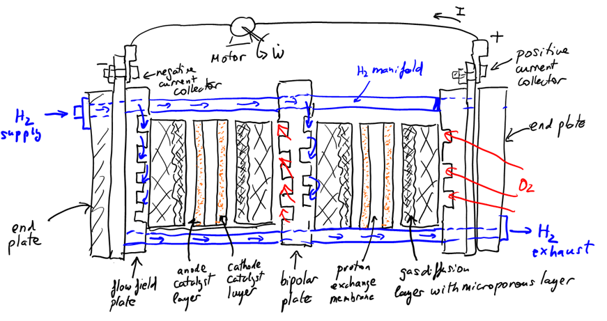
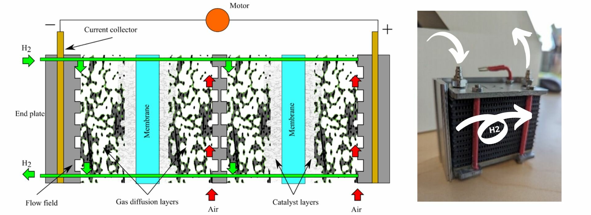
In summary, a single proton exchange membrane fuel cell is made up of a catalyst coated membrane (CCM), i.e., the proton conductive membrane coated with a catalyst layer on each side, sandwiched between two gas diffusion layers with a microporous layer. This assembly, known as a membrane electrode assembly (MEA), is finally sandwiched between two flow field plates. Since water will be produced during operation, the gas diffusion layers and microporous layers are usually coated with a hydrophobic agent, usually polytetrafluoroethylene (PTFE). In fact, the binder in the MPL is this same polymer. A schematic of a stack with two cells is shown below with all components labelled.
Fuel Cell Stack Arrangement
Now that we know how a single proton exchange membrane is assembled, it is now much easier to understand how a fuel cell stack is assembled. The two key questions now are: a) how do I connect individual cell together?, and b) how do I distribute the gases to all the cells?
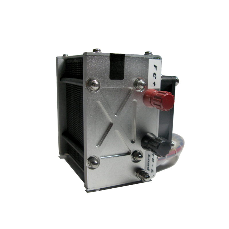
To connect cells together, the flow field plate between cells is replaced by a bipolar plate which contains two sets of channels, the flow field for the positive (cathode) electrode of the left cell, and the flow field for the negative (anode) electrode of the adjacent cell to the right. This plate is then both the positive and the negative current collector, hence its name, bipolar plate. Electrons can then freely travel from one anode to the next cathode. In low power applications, the cathode flow field is made of large parallel channels that are open to atmosphere and where the air flow is induced by a fan placed on one side of the stack. These type of cells are known as air-breathing cells and an example of such flow field is the cathode of a Horizon H-100 stack. In high power applications, the cathode flow field is closed and a compressor is used to distribute the power to each cell in an arrangement that is similar to the anode flow field. If liquid cooling is used to control the stack temperature, cooling channels can also present in the bipolar plates.
To distribute the hydrogen to all the cells in the stack, an inlet and outlet manifold are used. The inlet manifold is a large channel/pipe that connects the hydrogen inlet, which is connected to the hydrogen supply, to the inlet of the flow field in each fuel cell. Similarly, the outlet manifold is a large channel/pipe that connects all hydrogen flow field cell outlets. The inlet manifold is usually at high pressure while the outlet manifold is at lower pressure. In small scale applications the outlet is directly connected to the ambient, and water and any excess hydrogen is periodically purged. In applications where efficiency is paramount, the hydrogen is recirculated by increasing its pressure and mixing it with supply hydrogen.
Conclusion
This concludes our description of the main components of a PEM fuel cell stack and its operation, and therefore our first article. To summarize, the main components of a PEMFC stack are two end plates, two current collectors, a collection of single PEMFC, held together under compression by the two end plates in order to minimize electrical contact resistances. Each PEMFC is made of a membrane electrode assembly sandwiched between two bipolar plates that receive hydrogen from a hydrogen supply via a main hydrogen manifold, and air from the atmosphere either via a fan that sucks air via an open cathode flow field in each PEMFC or via a compressor and an air manifold. Current is produced due to the oxidation of hydrogen in the anode, and the corresponding oxygen reduction reaction in the cathode.
For proper PEMFC stack operation, it is important that the temperature and hydration of the PEMFCs in the stack is properly controlled and that each cell provides similar voltage to avoid damaging the stack. How should I operate my stack to achieve optimal performance? What is the effect of temperature, relative humidity and oxygen concentration on the PEMFCs in the stack? If you are interested in these questions, please stay tuned for my next blog. Do you have other questions, please send us your question at [obfuscate_1_|96|108|105|97|55|100|117|95|102|90|99|108|102|109|95|109|112|40|93|102|107].
Marc Secanell
Professor of Mechanical Engineering

Marc Secanell is a Professor in the Department of Mechanical Engineering at the University of Alberta, Canada, and the director of the Energy Systems Design Laboratory. He received his Ph.D. and M.Sc. in Mechanical Engineering from the University of Victoria, Canada, in 2008 and 2004, respectively. He holds a B.Eng. degree (2002) from the Universitat Politècnica de Catalunya (BarcelonaTech). In 2008, he was an Assistant Research Officer at the National Research Council of Canada, Institute for Fuel Cell Innovation in Vancouver, Canada, and 2015-16 and 2022-23 he was a visiting research scholar in the Energy Conversion Division at the Lawrence Berkeley National Laboratory (US) and at Johnson Matthey Technology Center (UK) respectively. He has authored over 80 journal articles, 30 conference proceedings and four book chapters receiving over 4,000 citations (h-index: 38 in Google Scholar).
Google Scholar: https://scholar.google.ca/citations?user=NjRIwW0AAAAJ&hl=en